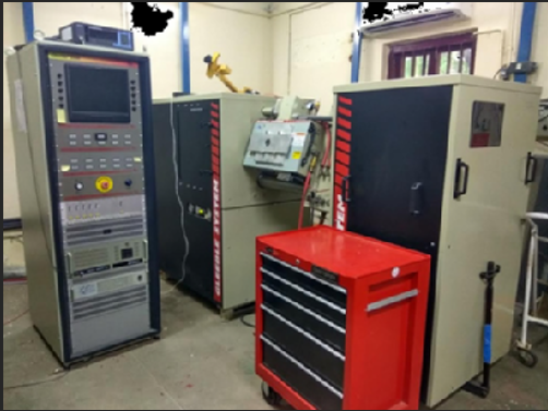
1.Gleeble 3800 system
·
The Gleeble
3800 is a fully integrated digital closed-loop control thermal and mechanical
testing system. Feature like, easy-to-use Windows OS based computer software in
combination with an array of powerful processors provides user friendly
interface to create, run and analyze the data from thermal-mechanical tests and
physical simulations programs. Gleeble 3800 system uses direct resistance
heating system to heat the specimens at rates up to 10,000°C/second, or can
hold steady-state equilibrium temperatures.
·
General
Specifications of Gleeble 3800 System:
1. Maximum heating rate - 10,000°C/second;
2. Maximum cooling rate - 10,000°C/second with water
quenching system;
3. Maximum stroke rate - 2000 mm/second
4. Maximum force - 10 ton in tension and 20 ton in
compression mode.
5. Specimen:-
Specimen Geometry: Round, Square and Flat geometry.
Specimen Size: (a) 5 mm dia. - 20mm dia. for Round
specimen;
(b) 5 mm - 20 mm square for Square specimen;
(c) 2mm - 5mm thick for Flat specimen.
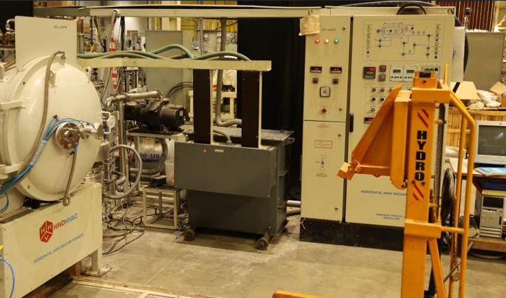
2.BRAZING FURNACE
This is a PLC (Programmable Logic Control) controlled High Vacuum
Furnace with Data Acquire Software SCADA (Supervisory Control and Data
acquisition). Brazing is done either in high vacuum environment or inert gas
environment.
Brazing furnace can operate in following three modes:
1. High Vacuum Heating, High Vacuum cooling;
2. High Vacuum + Inert gas heating, Natural or
Fast cooling
3. Inert gas Heating and Inert gas cooling.
Parameters of Vacuum Brazing Furnace:
1)
Heaters: Molybdenum strip;
2) Hot
zone: 350mm(width) x 150mm(height) x 500mm(depth)
3)
Maximum Charge Weight: 75kg
4)
Temperature Uniformity: +/- 5 C
5)
Heating rate : Programmable From 1 c/minute to 25 c/minute
6) Rapid
cooling :Gas fast cooling using Internal blower and Heat exchanger
3.METALLOGRAPHIC LAB
FACILITIES
·
Metallographic equipment(s) generally include sample cutting,
grinding, mounting, polishing, etching, microstructural analysis etc. Depending
upon the requirement of the application, following equipment(s) can be used to
obtain proper sample preparation techniques.
Following are the metallographic lab equipment in the division:
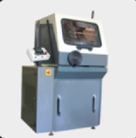
i.
Abrasive Cutting Machine
Usage: Machining of specimen, Tungsten tile machining, CuCrZr tube
& block, SS pipes & block etc.
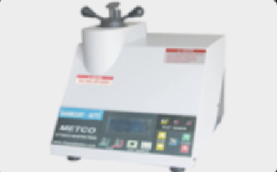
ii.
Pneumatic Mounting Press
Usage: Making of moulding of different sizes specimens, Automatic
cooling system
iii.
General Purpose grinding Machine
Usage: Rough grinding of specimens, plate, tiles, copper block
etc.
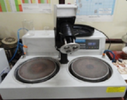
iv.
Semi-automatic double disc polishing machine
Usage: Polishing of specimens, fine polishing using different grit
size SiC papers, Mirror finish polishing using diamond paste on velvet cloth
etc.
v.
Metallurgical Microscope -Image analysis software-CCD colour camera
Usage:
Optical microstructure analysis of specimen.
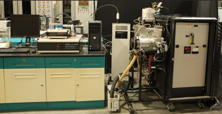
4.Laser Flash System
Principle:
Principle and working
method of equipment is as per ASTM E1461. A small, thin, disc specimen mounted
horizontally or vertically is subjected to a high-intensity short duration
thermal pulse. The energy of the pulse is absorbed on the front surface of a specimen
and the resulting rear face temperature rise is measured. Thermal diffusivity
values are calculated from the specimen thickness and the time required for the
rear face temperature rise to reach 50% percentages of its maximum value.
System also measures the specific heat capacity of a material by comparative
method.
System Details:
System consists of
remote-controlled Class I Nd: glass laser with maximum power 35 joules.
Ultrahigh tungsten furnace works under Vacuum (up to 10-6 torr) or
argon atmosphere with operating temperature range RT to 2100°C. It
consist room temperature add-on module with temperature range RT to 200°C and
LN2 cooled InSb detector for rear surface temperature measurement.
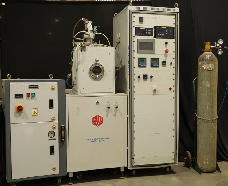
5.Magnetron Sputtering
System
·
IPR RF Magnetron Sputtering Unit (BC-300) make HHV, Bangalore is
having maximum capacity of RF power of 300W and substrate heating up to 1,000 oC.
The vacuum chamber can work at high vacuum of the order of 10-6 mbar. Metal targets like Ti, Cu, Cr, Al etc. and Non-metal like
Graphite target are normally used. This unit provides a complete coating
solution for the deposition of both metals and non-metal on various substrates
with good control of uniformity.
The major components of the unit are:
·
Vacuum
pumping system (HHV make FD-12 Rotary pump as primary, Edwards Next-400 Turbo
Pump as secondary pump).
·
Provided
gas (like Argon) purging line in the vacuum chamber during the sputtering
process.
·
PLC
vacuum controller, HMI touch control panel.
·
The 4
inch substrate heater cum substrate holder with rotation facility mounted on
the base plate of the vacuum chamber.
Water chiller for
continuous cooling the vacuum chamber & Magnetron.
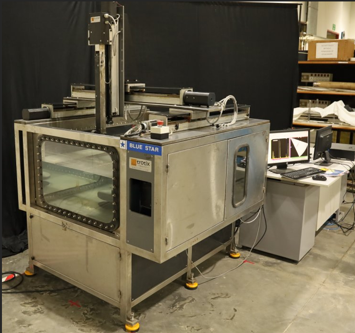
6.Ultrasonic Immersion
System
Principle:
Ultrasound uses high frequency sound waves to achieve this,
typically in the region of 0.1 - 35 MHz. In Immersion testing the object is
immersed in water, the water acts as the couplant between the source of
ultrasound and the material. Omniscan MX (Make: Olympus) is used as Contact
Ultrasonic Testing and this system combines with automated immersion system in
which the ultrasonic probe is manipulated by a motion controller.
Immersion testing offers the following advantages compared with
the contact method: - (a) Water coupling eliminates the variability associated
with contact coupling; (b) High frequencies, up to 35 MHz can be used; (c) High
resolution Scan up to 0.1mm step for C-scan imaging. (d) Scanning Area 900mm x
700mm x 700mm. - 300mm Dia. Turntable Rotating Chuck (e) A 6-axis manipulator
for maneuvering the probe head. (f) Horizontal IRIS to inspect PFC Monoblock
assembly.
The system shown in
Figures has high frequency capability (25MHz), enabling extremely fine
focusing. The pulser/receiver operate under the control of Tomoview software.
This collects the entire waveform and enables the data to be presented in a
variety of views (plan, cross-section, etc.). The probe manipulator has 2
degrees of freedom. Horizontal IRIS (Internal Rotary Inspection System) has
been developed and which is being used to inspect a PFC Mock-up assembly of
length 500mm to detect bonding defects. The tank can accommodate components
that are up to 0.7m x 0.9m.
The system is equipped
with a dedicated ultrasonic data analysis system (Tomoview), together with
integral scanner controllers designed by Trotix Ltd. (IIT-Chennai).
7.Eddy Current Test
system
Eddy Current Testing (ECT) is a non-destructive testing method
which utilized the principle of electromagnetism to characterize the integrity
of electrically conducting structural materials and components. A Portable Eddy
Current Test System (Model: Eddycon C, OKOndt Group) is recently set-up at High
Temperature Technologies Division, IPR. A system consists of Eddy Current
flaw detector, surface and bobbin eddy current probes, calibration standards to
detect surface and sub-surface defects presents in materials and components.
This facility have a potential utilization such as,
1. To check the
surface defects in Divertor plasma facing components at various stages of
manufacturing as well as at in-service inspection,
2. To evaluate
electrical conductivity of material and
3. To inspect raw
materials, multilayered structures and tubes.
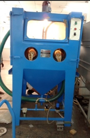
8.Sand blasting machine
IPR has sand blasting machine (Model SB 9182) make of M/s.
Abrablast. This medium size sand blasting machine works on induction – suction
principle of abrasive delivery. Mostly of smaller and medium size job are used
to clean to achieve fine matter finish. Material surface can also be roughened.
The blaster machine has incorporated with reclaimer that ensure
uniform cleaning and finishing each time and in every operation. This is
achieved by an automatic abrasive cleaning system built into the reclaimer. The
dust and debris are separated and only clean and sized abrasive are carried to
blast ensuring a homogenous finish.
Suitable size job holder can be used to restrict the movement of
the job during the sand blasting inside the cabinet. In a quick time, the job
surface can be cleaned even for very hard surface like tungsten materials can
be roughened.
Dimension Details:-
l
Working chamber size
(Width × Depth): 700 × 820 mm
Approximate
area can be covered for sand blasting is 400 × 400 mm (Width × Depth)
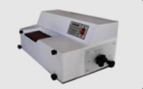
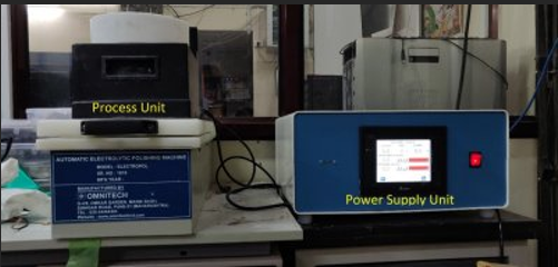
9.Electro Polishing and
Etching machine
Scope of
equipment: Electro polishing and etching machine is used widely for the
metallography of specimen/samples such as stainless steels, copper alloys,
Tungsten and Tungsten alloys, etc. Eletcro Polishing and Etching includes very
fine polishing (less than 1 micron) followed by revealing the microstructure of
a specimen using suitable electrolytes.
Make:- M/s.
Omni Tech, Pune
Model:-
Electopol
Technical
Specification (major):
1.
Polishing Voltage: 0 to 110 V DC
2.
Polishing Current: 0 to 10 Amp
3.
Etching Voltage: 0 to 15 V DC
4.
Etching Current : 0 to 2 Amp
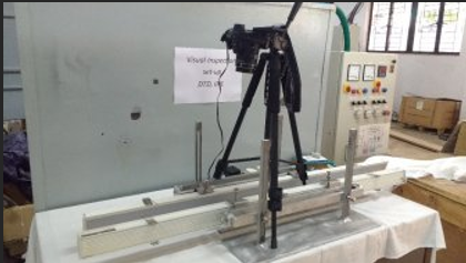
10.Visual Inspection
Set-up
Scope of
work: Visual inspection is a
nondestructive testing technique that provides a means of detecting and
examining a variety of surface flaws, such as corrosion, surface contamination,
surface finish, and surface discontinuities on joints (for example, welds, etc.)
using high illumination grazing light source.
·
Technical Details:
Light Source: High Illumination LED light
Illumination: ~ 4000 lux
11.2D and 3D Digital
Image Correlation (DIC) System
DIC method is a powerful technique for measuring material strain
deformation field. By comparison of digital images of the un-deformed and
deformed configuration, DIC provides full - field displacements to sub-pixel
accuracy and full–field strains in recorded images. 2D and 3D-DIC system is
established at High Temperature Technologies Division, IPR using a single
monochrome high speed imaging camera (1280x1024 pixels @ 2000 fps, Make Photron
Inc.) and open source software for full-field strain measurement. DIC system
have a potential utilization like (1) Material property and strain field
characterization during tensile testing, (2) Strain induced on
component/material due to temperatures (in high/Cryogenic regimes) and (3)
Transient strain behavior during mechanical testing.
High Speed Camera features:
·
1280 x
1024 resolution up to 2,000fps.
·
1280 x
720 (720p) resolution up to 3,200 fps.
·
12 bit
Dynamic range.
·
3.9
µsec Minimum exposure time.
·
8GB
Memory configurations.
·
ISO
Sensitivity: 10,000 monochrome.
·
Fame
rate synchronization with external trigger
·
Non-contact inspection with immediate full - field displacements
results.
·
Open
source DIC software analyzes strains, displacements, velocities, accelerations,
rotations, angles and changes in angle.
12.Portable CMM
Portable coordinate
measuring machines (PCMMs) are flexible tools for quality control. 3Dmeasuring
arms are used for dimensional verification, alignment for assembly,
CAD-comparison inspection, 3D scanning, reverse engineering, product
development, rapid prototyping, tube geometry inspection, and many other
quality control, inspection and verification applications.
Romer Sigma Portable CMM
can measure with the accuracy of +/- 0.100 mm. It has shown the capability of
measuring the large size object with high accuracy. It can measure the object
within 5m diameter without shifting the machine. This system will be useful for
the measurement of divertor systems because it requires accurate measurement
due to close tolerances.
13.Helium Leak Detection
Facility
We are using Pfeiffer Vacuum Helium Leak Detector to check the
leak in various vacuum systems. This is a microprocessor-controlled
leak-detecting equipment. All the processes in the instrument are controlled
automatically. Leak detection in vacuum and sniffer mode is possible by this
equipment. HLT 560 leak detector is having wireless remote control facility.
Which is highly useful in leak detection of a large vacuum system.
·
Technical Data :-
Smallest detectable leak rate of He (Vacuum leak detection
<5x10-12 mbar l/s)
Smallest detectable leak rate of He (Sniffer leak detection
<5x10⁻⁸ mbar l/s)
Test Method:- Vacuum and Sniffer
Detectable gas :- 4He,3He,H2
Internal He-Test leak 10^-7 mbar l/s
Leak rate display 10^-12 - 1 mbar l/s
Cold start to ready 3min
Response time 0.5sec
Flange (In) DN 25 ISO KF
Inlet pressure Max 25mbar
Ambient temp 10-35 C
Interface: - RS232-C, RS485
Power Consumption: 400VA
Analog Out Put: - Leak rate signal 2x0-10V lin/log
Digital-output:
- Ready to start, Ready to measure, Leak error, Bypass valve,
Calibration,Acknowledge
14.High Heat Flux Test
Facility
HHF
introduction:-
High heat flux test
facilities of various kind are being used worldwide to investigate the
performance of plasma facing materials/ mock-ups/ components under estimated
thermal load conditions in various plasma fusion devices. The high heat flux
test facility has been set-up at IPR to perform thermal load testing of plasma
facing materials/ mock-ups /components. It is equipped with a high power
cylindrical electron beam used as heat source having maximum beam power of 200
kW @45kV having static and dynamic deflection angle of +/- 25 and +/-10 degree
respectively that allow testing of large size components up to 2m (W) x 1.2m
(H)surface area. The beam can be operated to simulate quasi-steady state as
well as transient heat loads over test objects by either rastering it over test
object at high frequency (up to 10kHz) or by operating it in pulsed mode (t
> 1ms). The electron beam is horizontally mounted on a large volume (~ 7 m3)
D-shaped double-walled vacuum chamber with target-handling facility that can
handle large sized test objects weighing up to 2 ton. High pressure Water loop
system, High pressure Helium loop system, Thermal diagnostic systems and Data
Acquisition & Control system will be integrated with the facility for
testing water cooled as well as helium cooled plasma facing components.
Features of HHF test facility
Simulation of ITER and DEMO specific thermal loads on plasma
facing components viz. Divertors and First Wall Components.
Thermal fatigue testing of divertor and first wall modules.
ELMs simulation experiments for materials testing.
High Pressure High Temperature Water and Helium coolant loops.
Validation of materials, designs and joining process on small size
test mock-ups as well as full-size fabricated components.
Vacuum chamber having more than 50 diagnostic ports with several
sophisticated thermal and calorimetric diagnostics.
Sophisticated Data Acquisition & Control system.
1.
Vacuum Chamber
A D-shaped configuration
type vacuum chamber has been successfully fabricated and commissioned along
with the electron gun for high heat flux testing. The electron gun is projected
horizontally from backside and will be supported separately with a separate
arrangement. The dimensions of the chamber are: Diameter 2.4 m, Height 1.5 m
with double wall cooling system to accommodate full-scale mock-up of size: 2.0m
x 1.2m x 0.8 m. The mounting of test mock - up / components are carried
out on target handling arrangement which is also a front door for closing the
chamber. The door has feed-throughs for connecting high pressure systems to the
test mock -ups. The position of diagnostic ports are designed in such a way
that all the ports can view the total area of the mock - up such that the data
at any point on the mock - up can be easily done through the diagnostic
devices. The salient features of the vacuum chamber are that small scale
to full scale testing of mock ups / components can be done. The ~7m3 D-shaped vacuum
chamber has over 50 ports for diagnostics and views of the target and
4500 l/s (N2 gas)
cryo pump and 1900 l/s (N2 gas) turbo molecular pumps are used for creating vacuum pressure of 10-6 mbar.
2.
Electron Beam System
High power electron beam
gun EH 300 V manufactured by M/s Von Ardenne, Germany, has been installed,
commissioned and tested successfully. The maximum beam power is 200kW for 12mm
diameter cathode and the beam power is controlled by a patented VARIOCATHODE
mechanism. Power below 20% are achieved by a reduction of the cathode
temperature. The beam acceleration voltage is variable in the range between few
kV up to 45 kV, whereas the maximum power is only reached at acceleration
voltages of 45 kV. To enable the simulations of very short event types in the
millisecond range, a high voltage pulse mode has been integrated. In this case,
the beam power is controlled by a predefined cathode position, and a pulse
repetition rate of up to 10 kHz can be defined. A system of two magnetic lenses
is used to focus the beam. By additionally optimizing the process chamber
pressure, the electron beam diameter can be reduced to reasonable size.
The total deflection angle of the EB is limited by the dimensions of the process
chamber to +/- 33 degree. The process chamber and the two vacuum chambers of
the EB-gun are effectively separated. This enables very flexible pressure
optimizations and additionally access to single components with short process
interruption times.
3. High pressure high temperature water circulation system
HPHT-WCS
The high pressure high
temperature water circulation system (HPHT-WCS) has been designed to cool down
the test mock-up which is connected to the HHF test facility. The test mock-up
connected to the water circulation loop has a maximum heat load of 210 kW. In
this test loop de-mineralized water (D.M water) is used as a working medium and
system can operate in the pressure range of 5 bar to 60 bar and the temperature
range of 25 degree C to 160 degree C with a maximum flow rate of 300 LPM. Inert
gas pressurization method is used to pressurize the DM water in the pressure
vessel using nitrogen. The nitrogen source (bank of nitrogen cylinders)
connected with pressure vessel and a pneumatic pressure regulator controls flow
of nitrogen in to the pressure vessel. The data acquisition system (DAS) with
instruments is installed along with the test facility to record and control the
test parameters pressure, temperature and flow rate. The test loop is designed
as per relevant safety standards.
The major components of
the test loop are reservoir tank, two positive displacement pumps with motor,
pressure vessel with accessories, bank of nitrogen cylinders, two booster pumps
with variable frequency drive, vortex type flow meter, heater bank, cooling
unit, different types of valves at various locations, safety devices, pressure,
temperature, level and other sensors/ indicator/transmitters with controllers.
A detailed engineering design of various components like pressure vessel, heat
exchanger, cooling tower along with thermo hydraulic analysis has been carried
out.
4. Integration of EHCL with Helium Cooled Target handling System
(HTS):-
Experimental Helium Cooling
Loop (EHCL) of Fusion Blanket Division is integrated with Helium cooled Target
handling System (HTS) of HHFTF for supplying high-pressure, high temperature
helium gas to the gas cooled plasma facing components. Helium gas is supplied
by EHCL at maximum inlet temperature of 400ºC, maximum Inlet pressure of 80 bar
and maximum flow rate of 400 g /s. Supply and returns lines are routed between
EHCL and HTS and they are connected to a pipe header assembly.
14.1Portable Water
Circulation System (PWCS)
The
main function of portable water circulation system is to actively cool the test
mock -ups (loads) which are supposed to receive heat loads that represent
normal and off - normal thermal conditions. The PWCS typically consists of
components such as high-pressure water pump with a control unit, corrosion
resistant (stainless steel) water tank with built-in heater for heating and
storage of water, calorimetric (temperature, pressure and flow rate of water)
monitoring & diagnostic sensors, display unit and feedback control system.
The operating parameters of the system is to circulate water at high pressures
up to 20bar, high temperatures up to 80 deg C and high flow-rates up to 100 LPM
through test mock-up tubes having inside diameters in the range 10mm-25mm and
length up to 500 mm.
14.2Temperature
measurement and calibration facility
· Temperature Measurement Facility up to 3000 C:
Temperature measurement
facility include instruments capable to measure temperature from 200 C to 3000
C with high accuracy and fast response time. For higher temperature
measurements non-contact type IR Cameras and Pyrometers are used.
14.3Nitrogen Generation
Setup (NGS)
·
Nitrogen generation setup is a facility possessed by High
Temperature Technology Division (HTTD), which extracts Nitrogen from air and
supply to the required system inlet.
· Operating Parameters of the System:-
·Pressure at the outlet of the system 05 bar to 20 bar controlled
by PRV
·Flow rate of the Nitrogen gas 10 Nm3/hr.
·Purity of the Nitrogen gas generated at the outlet >99.00%.
·Application
of NGS:-
·Although Nitrogen gas has versatile application in
scientific work, but in HTTD, Nitrogen gas is used as pressuring
gas to water in HPHT-WCS’ pressure vessel. Also Nitrogen gas is currently being
used for venting of High heat flux Vacuum chamber.
14.4Differential Pressure
Transmitter
Pressure
drop studies are very important in the view of single and two phase flow
distribution and safety parameter like Critical Heat Flux (CHF). The pressure
drop first decreases with increase in heat flux due to decrease in near wall
viscosity until it reaches to some critical point between ONB (Onset of
nucleate boiling) and OSV (onset of significant voids) then it increases with
further increases in heat flux due to increase in void fraction and ultimately
reaches to CHF. It may be noted that pressure drop fluctuation due to bubble
induced turbulence in subcooled two phase flow is also important, which
enhances further by increase in void fraction. The DPTs at HHFTF have high
accuracies to measure the pressure drop during heat flux tests.
14.5Liquid Tin-Lithium
(Sn-Li) Alloy Production System
The
Sn-Li production system is established to produce the liquid Sn-Li25at% alloy
for the application of liquid metal-based PFC. The facility is capable to
produce ~8.0 Kg (~1.3L volume) of Sn-Li alloy in one batch. The operating
temperature of system is RT to 350C and pressure up to 5 bar (Argon gas). The
system consists of SS 316L pipes and SS 316L tanks mounted on MS support
structure. The major components of the system are; Rotary vane vacuum pump,
Electro-magnetic stirrer, Control panel, Heaters (wire/Jacket type), Pressure
and Vacuum Gauges, Thermocouples.
15.Small Specimen
Testing of Mechanical Properties
·
Small
specimen tensile testing techniques are developed for evaluating mechanical
properties of the materials using Gleeble 3800 system. Small specimen testing
techniques are useful for evaluating the mechanical properties of materials
using very limited sample volumes. Small Specimen Tensile Tests, Shear
Punch Tests and Small Punch Tests can be performed using Gleeble 3800 system.
Small Specimen Tensile Test:
Sample Size: Gauge length – 10 mm,
Gauge width – 2 mm, Thickness – 2 mm , Overall length - 30 mm
Test Temperature: 200°C to 1700°C
Environment: 10-3 torr
vacuum or Inert Gas like Argon and Nitrogen.
Shear Punch Test and Small Punch
Test
Sample Size: 8mm (d) x 0.5-1mm (t)
Test Temperature: RT to 700°C
Environment: 10-3 torr
vacuum or Inert Gas like Argon and Nitrogen.